Assessment
Methodology for Environmental Assessment: Defining principles, requirements, and guidelines for the quantification of CFPs
GHGs can be emitted and removed throughout the life cycle of a product which includes the acquisition of raw material, design, production, transportation/delivery, use, and end-of-life treatment. Quantification of the carbon footprint of a product (CFP) will assist in the understanding and action to increase GHG removals and reduce GHG emissions throughout the life cycle of a product. This document details principles, requirements, and guidelines for the quantification of CFPs.
Accounting Procedures & Standards
HydroLink’s GHG emissions accounting procedure utilises emission protocols and the internationally recognised standards derived from the International Organization for Standardization (ISO) to assess the carbon footprint (and other impacts) of fuel production. IPHE adopted three of the eight principles defined in ISO 14040 (environmental management - life cycle assessment (LCA)):
Goal and scope phase (ISO14067)
Life cycle inventory (ISO14040)
Lifecycle impact assessment (ISO14044)
Principle 1: Requirements - Goal and Scope
Principle 2 & 3: Requirements - (Life Cycle Inventory and LCIA phase)
Reporting Framework & Boundaries
As part of the methodology devised by the IPHE, production boundaries will be defined. This indicates which stages of the hydrogen production value chain will be subject to GHG emission monitoring. As taken from the report, this methodology is based on the principles of:
inclusiveness (methodologies should not exclude any potential primary energy);
flexibility (approaches must allow for unique circumstances and hence flexible);
transparency (methodologies must be transparent in approach and assumptions to build confidence);
comparability (approach should be comparable with the approach used by other technologies to help allow for ‘apples to apples’ comparisons on emissions); and
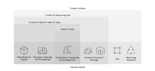
practicality (methodologies must be practical, facilitating uptake by industry and use in the market). Referring to Figure 2, the ‘well-to-gate’ boundary is seen by IPHE stakeholders as the preferred starting point in defining the system boundaries.
Figure 2: System Boundaries
The ‘well-to-gate’ boundary would encompass all GHG emissions emanating from the collection of production inputs, transporting them for pre-processing, and final good production. It excludes elements of the value chain beyond production, such as the transportation of hydrogen to consumption sites, its use, and its end-of-life treatment. The environmental impact caused by the construction, manufacture, and decommissioning of goods, peripheral assets held by the firm in question, business travel and employee commuting is not considered within these boundaries. The logic behind this reduced scope of the Hydrogen procurement process is largely driven by the relatively minor emissions resulting from these practices relative to the emissions associated with the production process itself for both renewable and non-renewable hydrogen.
Environmental Audit
To leverage the benefits of the HydroLink platform, hydrogen producers will connect pre-configured IoT devices to their production equipment. Sensory equipment is capable of accurately recording geolocation and environmental conditions - including temperature, humidity, and pressure levels. Dedicated embedded algorithms will parse the raw physical machine data, and subsequently, compare it against the standardised data pool. The design of the parameters embedded in the smart contracts will execute in accordance with the globally recognised IPHE emission standards. A summary report of these interactions is generated and recorded on the blockchain, providing exhaustive referential data, which companies can use to refine and optimise their practices. Further, IoT devices across the stages of the supply chain that are excluded from the IPHE recommended guidelines will be subject to traceability.
Electrolysis
As described in section 4., an electrolytic cell contains an anode and a cathode separated by a membrane and immersed in a conductive solution - or an electrolyte solution. Currently, there are three primary electrolyser technologies deployed - the alkaline electrolyser, polymer electrolyte membrane (PEM) electrolyser, and solid oxide (SOEC electrolyser). These processes can be differentiated by how the electrolyte is used, and the resultant production temperatures. Using a direct current power supply, electricity flows through the electrolyte solution to drive a non-spontaneous reaction in water causing water molecules to split into hydrogen and oxygen molecules. Each electrolyser system comprises a stack of electrolysis units, a gas purifier and dryer, and a cooling apparatus. The magnitude of greenhouse gas (GHG) emissions produced during electrolysis is determined based on the fuel source used for the catalysing electricity supply. Hydrogen isolated via electrolysis reliant on the combustion of gas, liquid, or solid fuel sources, make up most emission sources in the production process. However, if the initial energy stimulating electrolysis is derived from a renewable system, clean, or “green”, Hydrogen can be produced and certified as such. Based on these parameters for emissions accounting, electrolysers are generally assumed to possess an outlet pressure of 3 MPa.16
Emissions Sources in Electrolysis
GHG emissions resulting from electrolysis are contingent upon the nature of the supplied electricity for the process, as it can be sourced from power generated on-site using combustion methods for liquid, gaseous, and/or solid fuels, or supplied from an off-grid on-site system.
SMR/CCS Process Description
The steam methane reformer (SMR) is the most used technology for Hydrogen production from natural gas, or light hydrocarbons, in the current market. In SMR facilities, GHG emissions are created through the combustion of fossil fuels for heat and steam, and because of the reforming reaction. Modern implementations of this technology have allowed hydrogen production facilities to experience significantly improved efficiency in CO2 emission reductions. Synthesis gas, or syngas, is a gaseous fuel mixture consisting predominantly of hydrogen, carbon monoxide, and often some remaining carbon dioxide from the pre-capture process. Syngas is used as an intermediate stage in the production of synthetic natural gas, a form of gas created from coal that can be used as a substitute for natural gas and is capable of transmission in natural gas pipelines. De-sulphurated natural gas is heated, mixed with steam, and channelled through a steam reformer, producing synthetic gas. This catalyses an increase in the percentage of hydrogen in the synthetic gas mix prior to purification, resulting in isolated hydrogen. For both of these approaches - with carbon capture systems implemented - the CO2 compression needed for Carbon Capture and Storage (CCS) represents a sizeable emissions point in concurrence with the upstream emissions necessary to procure natural gas and coal.
Reductions in CO2 emissions beyond this point would only be feasible with the introduction of CCS. There are three basic types of CO2 capture: pre-combustion, post-combustion, and oxyfuel with post-combustion. Pre-combustion processes are designed to convert fuel into a gaseous mixture of CO2 and hydrogen, with the hydrogen being separated and burned without producing CO2 (which can be compressed for storage or transportation). Carbon Capture and Storage systems typically consist of:
Feedstock pre-treatment
Pre-former
Primary reformer
High-temperature shift reactor
Pressure swing absorption (PSA)
The industry standard for CO2 capture from an SMR H2 plant involves emissions capture from the shifted syngas using Methyl diethanolamine (MDEA) solvent. Other CO2 capture options can be integrated, including the capture of CO2 from PSA’s tail gas using MDEA, the use of Cryogenic and Membrane Separation, and the capture of CO2 from flue gas using MDEA. These options involve the CO2 capture rate in the range of 56% to 90%. The conversion processes required for pre-combustion capture are more complicated than those involved with post-combustion, making the technique challenging to adopt and implement for established power plants. Post-combustion processes segregate CO2 from combustion exhaust gases. CO2 can be captured with a liquid solvent or using other separation methods.
In an absorption-based approach, after the CO2 has been absorbed into a solvent it is released via heating to create a high-purity CO2 stream. This technology is ubiquitously used to capture CO2 as an input for the food and beverage industry. Oxyfuel combustion processes utilise pure oxygen rather than air for the combustion of fuel. This results in exhaust gas that is largely water vapour and CO2 that can be further captured, purified, liquified and commodified.
Emissions Sources in SMR/CCS
For steam methane reforming with CCS, the main source of GHG emissions is the conversion of natural gas (NG) to CO2. Other significant emissions sources include the scope 2 emissions of grid electricity, CO2 removal, and CO2 compression for CCS.
Final Reporting Requirements for Certification
Last updated